PW doppler is typically used for displaying the speed, direction, and spectral content of blood flow. This allows the user to perform measurements concerning the velocity of moving fluids. PW doppler lets you examine blood flow data from a small region called the sample volume, which appears graphically on the B‑ or B+Color image. You can move the sample volume to any location within the B‑mode or B+Color image.
In PW doppler mode, energy is transmitted from the ultrasound probe into the patient, as in B-mode. However, the received echoes are processed to extract the difference in frequency between the transmitted and received signals.
Differences in frequencies can be caused by moving objects in the path of the ultrasound signal, such as moving blood cells. The resultant signals are presented graphically on the system display. The X-axis of the graph represents time while the Y-axis represents velocity in either a forward or reverse direction.
Spectral Doppler display
When PW doppler is enabled, it starts updating from the left side of the screen. The baseline of the graph (representing zero velocity, zero frequency shift), appears as a solid line running horizontally across the display. By convention, movement toward the probe is positive and movement away from the probe is negative. Positive frequencies or velocities appear above the baseline. Negative frequencies or velocities appear below the baseline. Typically, blood flow is not uniform but is composed of a mix of blood cells moving at different velocities and in different directions. Strong signals are displayed as bright while weak signals are displayed as less bright.
Using PW doppler
Using PW Doppler mode might proceed as follows:
1. Select the preset and probe to be used.
2. Locate the anatomy to be examined. Get a good B-mode image. Enable color to help locate the vessel to examine.
3. Press  icon to access the additional modes to enter PW. The PW-mode is then activated and the PW cursor appears on either a frozen B- or B+Color mode image.
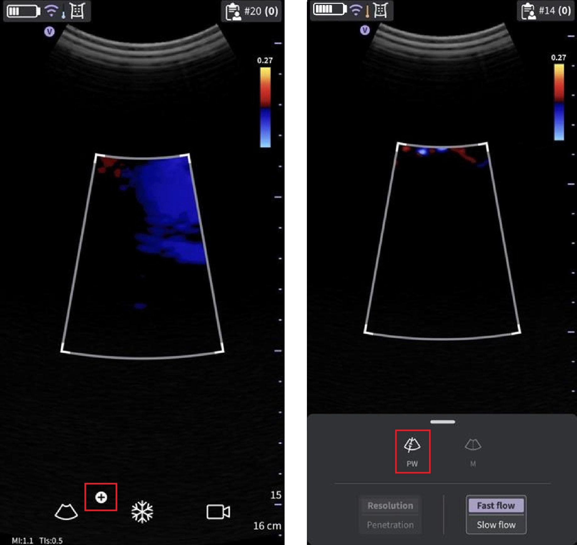 Activating PW from Color-mode
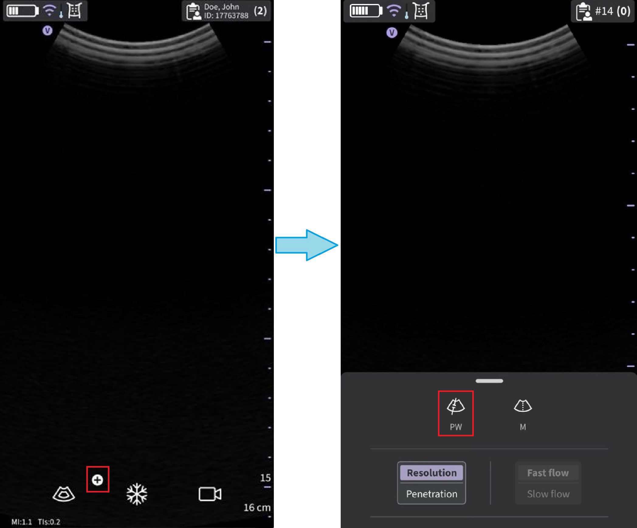
Activating PW from B-mode
4. To change the sample volume position touch anywhere in the B- or B+Color display area to activate positioning of the PW sample gate
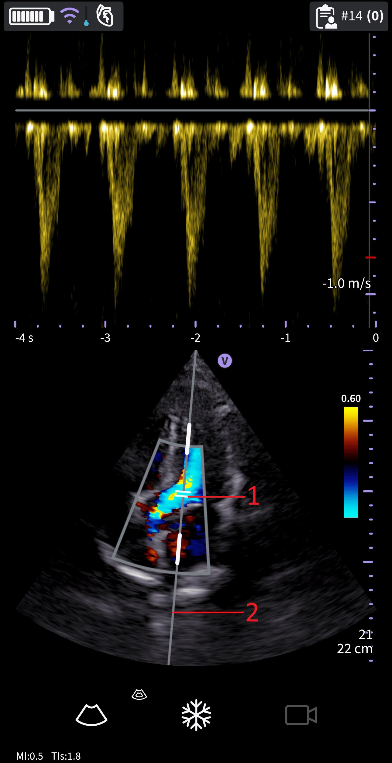 Sample volume positioning
1. PW Sample volume/Sample gate
2. PW cursor
5. Adjust angle correct (AC) by touching one of the ends of the angle correct line passing through the sample volume gate.
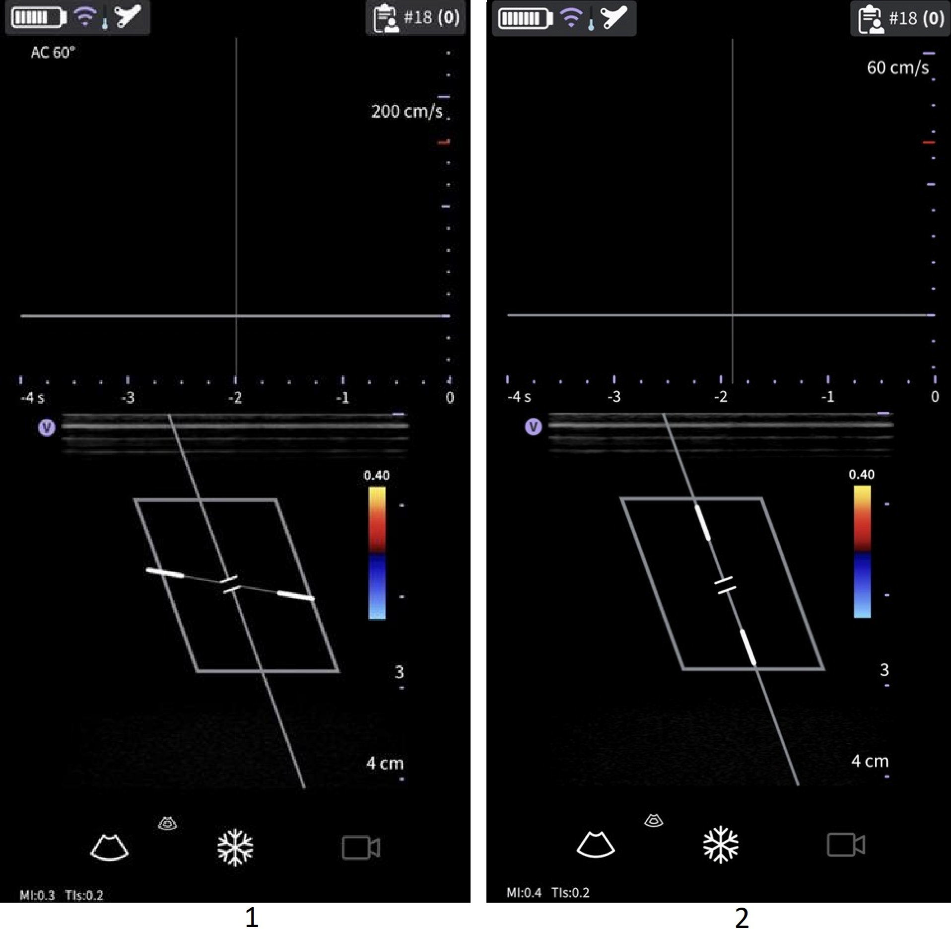
Angle correct value
1. AC 60 degree
2. AC 0 degree
- Angle correct defaults to 60 degree for Vascular presets and to 0 degree for all other presets
- The angle correct value displayed in the upper left corner of the PW spectrum is different from 0 degree.
6. To exit PW Doppler and return to B-mode press the icon. To exit PW Doppler and return to B+Color mode press the
 icon to exit PW Doppler.
Disclaimer: The information herein is not intended to replace the product’s User Manual. Please consult the User Manual for comprehensive information and cautionary guidance about the product’s operation and use.