Learn about the Color Imaging Scanning Adjustments like Color Gain, Position and Resize ROI, Color Steer and Color Aliasing
The Color flow (Color Doppler) mode is adding color coded qualitative information concerning the relative velocity (in m/s) and direction of fluid motion within the black and white (B-mode) image.
1. Press the Color icon.
A color flow area displays on top of the black and white image.

Entering Color flow
2. Drag the color Region of Interest (ROI) to the desired area. The color ROI outline becomes blue when active.
3. To exit color and return to B-mode press the  icon.
icon.
NOTE
• The color images can be zoomed by pinching the images with two fingers.
• The active gain control is disabled as long as the TGC controls are active.
Color Gain
Color gain amplifies the overall strength of echoes processed in the color area.
1. Swipe at least half a centimeter from the left or right on the scan screen to initiate gain.
NOTE: Small movements will be ignored to avoid unintentional activation of the color gain control.2. Move your finger to the right or left outside the color ROI to increase or decrease color gain.
Position and Resize ROI
The size of the Region of Interest (ROI) has an effect on the frame rate. The width of the ROI has a significant effect on frame rate even more than the height of the ROI. Keep the box sized just to the anatomy of interest and as close to center as possible.
Drag your finger inside the ROI to move and position. The box turns blue indicating that the controls for adjusting the ROI are activated. Use the controls on the corners to adjust size.
 Position and resize ROI
1. Move ROI
2. Resize ROI
3. Color/velocity bar
4. Nyquist velocity
Color Steer
Slant the ROI (Region of Interest) of the Color Flow linear image left or right to get more information without moving the Vscan Air CL probe.
Use the controls on the center top and bottom to steer the angle.
NOTE: Color steer applies only when using the linear array transducer of the Vscan Air CL.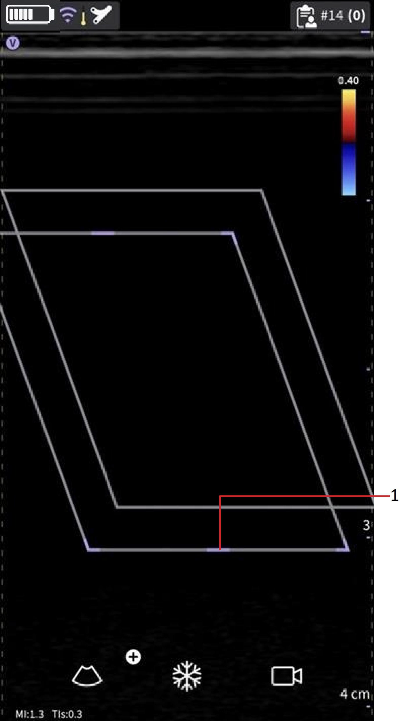
Steer color ROI
1. Steer ROI
Color Aliasing
If the blood flow velocity exceeds the Nyquist limit indicated by the number displayed with the velocity bar aliasing may occur.
CAUTION
When blood flow velocity exceeds the max velocity range covered by the device, color aliasing may occur, which results in incorrect velocity estimates
Aliasing appears as a shift in color from the color representing positive velocity to color representing negative velocity or visa versa.
Positive velocity indicates flow towards the transducer and negative indicating flow away from the transducer.
The maximum velocity or Nyquist limit is displayed on top of the velocity bar.
Fast and slow flow (High and low velocity scale)
For a few presets, there is a control available in the color flow mode for alternating between high and low velocity scales. A higher velocity scale is needed to avoid aliasing while imaging of faster (arterial) flow. A lower velocity scale optimizes the imaging of slow flow (venous).
The presets that support selection between high and low velocity scale are the following:
Curved array | Sector array | Linear array |
Abdominal | Abdominal | Vascular |
OB-GYN | OB-GYN | MSK |
Vascular | Cardiac | Small Parts |
Cardiac | TCD | Nerves |
| Cardiac Guidance* | ||
| Bladder Volume* | Bladder Volume* | |
| Lung Guidance* | Lung Guidance* | Lung Guidance* |
| * Preset is available or being used if the option to enable that preset or tool has been purchased. | ||
To change the velocity scale, tap either Fast flow or Slow flow to alternate between the velocity scales. The selected setting is highlighted. The velocity scale corresponding to the selected setting can be seen at the top of the velocity bar.
 Fast and slow flow
1. Fast flow setting
2. Slow flow setting
Disclaimer: The information herein is not intended to replace the product’s User Manual. Please consult the User Manual for comprehensive information and cautionary guidance about the product’s operation and use.